Full Adder Cmos Implementation
Conventional cmos full-adder, fa28t Carry generator (majority function) circuit. Cmos adder
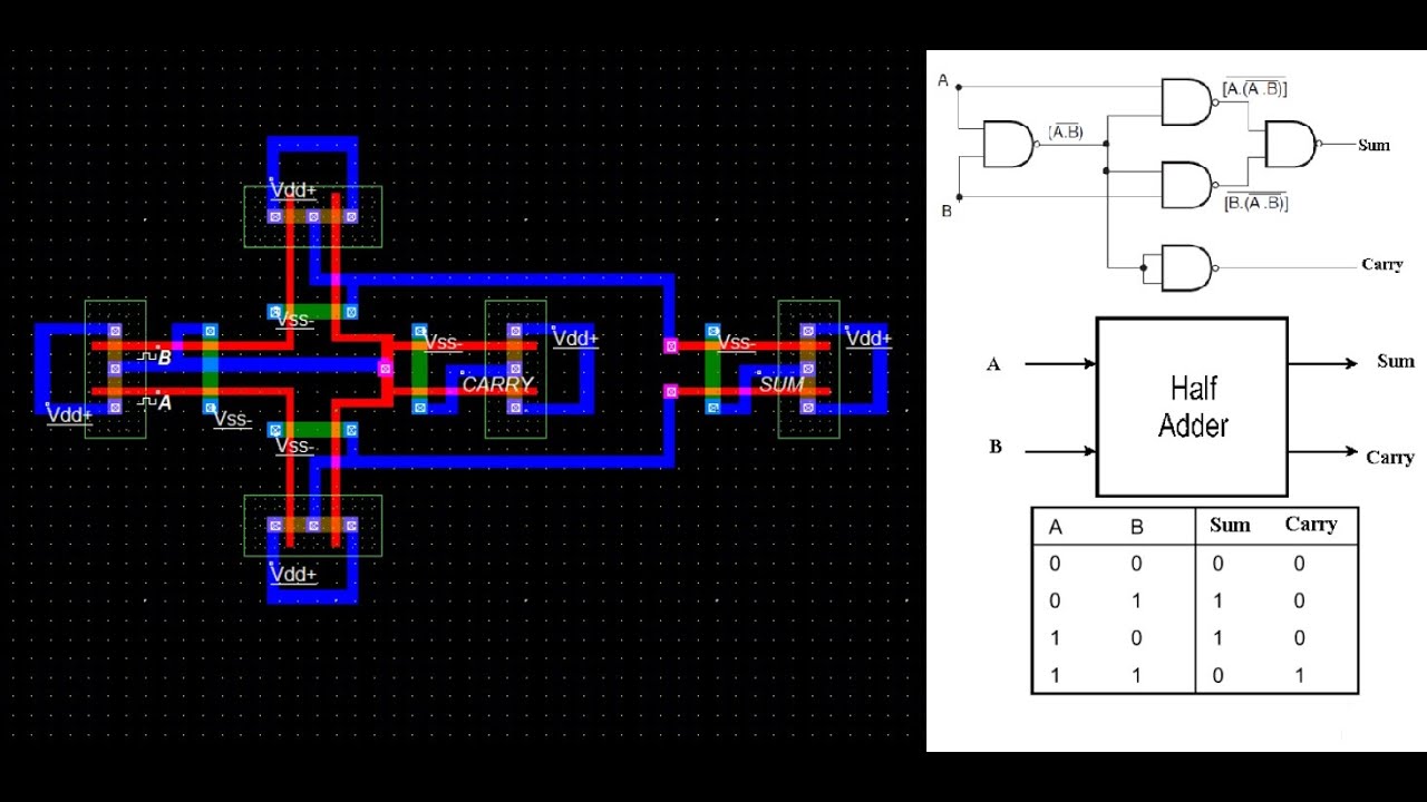
CMOS HALF ADDER USING MICROWIND SOFTWARE - YouTube
Adder half cmos using circuit implement sum carry Adder transistors Implementation of low power 1-bit hybrid full adder using 22nm cmos
A comparative study of full adder using static cmos logic style
(pdf) low-power and high-performance 1-bit cmos full adder cellFull adder cells of different logic styles. (a) c-cmos, (b) cpl, (c Adder cmos dynamic cell speed high figure noise lowAdder cmos implementation.
Adder cmos mirror understand stack works please help logic pmos circuit nmos network begingroupSchematic diagram of existing half adder using static cmos technique Digital logicCmos half adder using microwind software.

Cmos adder
Adder cmosImplement half adder circuit using static cmos. Adder cmos using schematic existingCmos adder conventional.
A high speed low noise cmos dynamic full adder cellWhy is a half adder implemented with xor gates instead of or gates Adder cmos comparative logicAdder cmos.

Tutorial on cmos vlsi design of a full adder
Adder gates half logic xor cmos mirror diagram implemented instead why schematic implementation optimized functionally equivalent construction just pipe stackCmos fast-carry full adder Full adder using 28 transistorsStatic cmos full adder.
Adder cpl cmos logic tfa tgaAdder cmos inputs majority .


